A 5G site is not simply a 4G site with a faster radio. The rectifier system behind it has to carry a different load profile, tolerate much larger short-term current swings, and still guarantee that the battery is recharged before the next outage. Sizing that system correctly is the difference between a site that rides through a grid failure and one that drops traffic at the worst possible moment.
This guide walks through the practical sizing method we use when specifying 48V telecom rectifier systems for 5G macro and pole sites: from the load budget, through redundancy, to the recharge check that most spreadsheets forget.
Why 5G Sites Change the Rectifier Sizing Math
Three things shift when a site moves from 4G to 5G:
Higher average load. Massive MIMO radios draw considerably more power than the 4G RRUs they replace, and the baseband unit does more processing per sector. A site that averaged 1.5 kW on 4G commonly lands in the 2.5–4 kW range on 5G.
Sharper peaks. Traffic-driven power draw on a 5G radio is bursty. The average may be 3 kW while the ten-second peak sits meaningfully above it. Rectifiers must supply the peak; batteries only cover the gap during an outage.
More sites, less space. 5G densification pushes equipment into cabinets and pole-mounted enclosures where thermal headroom is tight. A design that works thermally in a shelter may not work in a sealed outdoor cabinet.
Step 1: Build the DC Load Budget
Start from the equipment list, not from a nameplate total. For each item record the steady-state current at 48 V DC and the peak current.
Typical 5G Site Loads
- Baseband unit: usually the largest single continuous load after the radios
- Radio units (per sector): rated output power plus radio efficiency losses, multiplied by the number of sectors
- Transmission / microwave or fibre termination: modest but continuous
- Monitoring, fans, door sensors, lighting: small individually, non-trivial in aggregate
- Future expansion allowance: typically 15–25% headroom for an additional sector or a second tenant
Convert everything to amperes at the nominal bus voltage. Working in watts and dividing later is where mistakes creep in, because the bus is not exactly 48 V — a discharging battery sits well below it.
Average Load vs Design Load
Two numbers matter, and they are not the same:
Average load drives the energy calculation and therefore the battery size.
Design load drives the rectifier capacity. Use the peak, add the expansion allowance, and only then apply redundancy. Sizing rectifiers on average load is the single most common cause of under-provisioned 5G sites.
Step 2: Pick the DC Bus and Rectifier Output
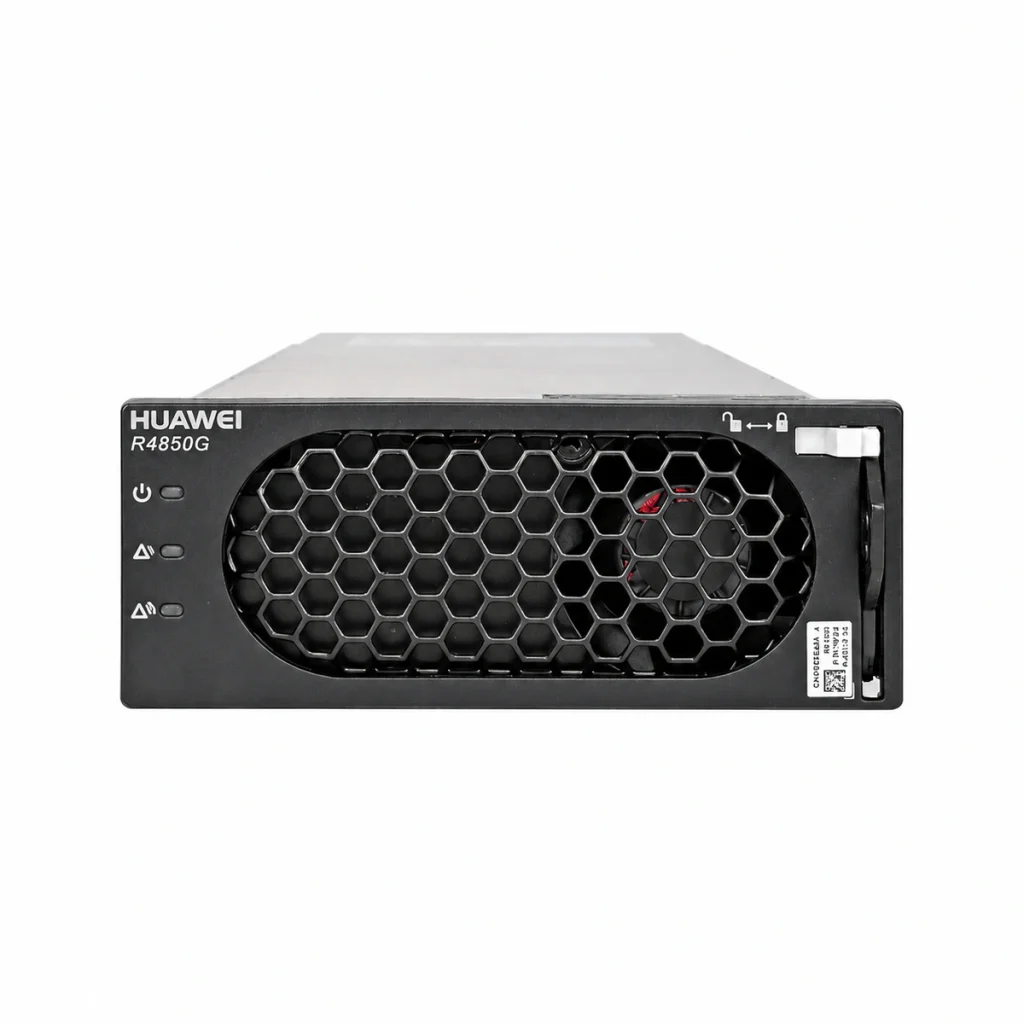
Telecom DC plants run a nominal −48 V bus. Rectifier modules are commonly available in the 1 kW to 4 kW class, with 48 V output and wide AC input range. Higher-output modules reduce the number of units and the amount of racking, but they also raise the minimum load per module and can hurt efficiency at light load.
Two practical rules:
Do not over-fragment. A dozen small modules cost more in racking, wiring and controller ports than four larger ones.
Do not over-concentrate. If a single module failure removes more than roughly a quarter of total capacity, the remaining units may not hold the load through the battery recharge window.
Where the site has a wide AC input range requirement — weak grid, generator back-up, long feeder runs — confirm the rectifier’s derating curve at low input voltage. Output power falls as input voltage drops, and a module rated 3 kW at 220 V may deliver considerably less at 150 V.
Step 3: Apply N+1 (or N+N) Redundancy
Redundancy is expressed in modules, not in percentages. The arithmetic is straightforward:
Modules required = ceil(design load ÷ module output) + redundancy
Worked Example
Assume a three-sector 5G macro site:
- Design load at the bus: 3.6 kW
- Selected module: 3.5 kW output at nominal input
- Redundancy: N+1
Modules for load alone: 3.6 ÷ 3.5 = 1.03, rounded up to 2. Plus one redundant module gives 3 modules, or 10.5 kW installed against a 3.6 kW load.
That looks generous, but check the failure case. With one module out, 7.0 kW remains — still comfortably above the 3.6 kW load, and with enough surplus to recharge the battery while carrying traffic. Now push the design load to 8 kW: five modules plus one gives 21 kW installed, and a single failure leaves 17.5 kW, still adequate. The point is that the redundancy check must be done on the post-failure capacity, not on the installed total.
For sites with a strict SLA, N+N is sometimes specified. Understand the cost: N+N roughly doubles installed rectifier capacity and often doubles the AC feed requirement, which may force a larger upstream breaker and feeder.
Step 4: Size the Battery, Then Verify Recharge
Battery autonomy and rectifier capacity are linked by one constraint that is easy to overlook: after the outage ends, the rectifiers must carry the site load and recharge the battery within an acceptable window.
Recharge current check: required recharge current is roughly the battery’s recommended recharge rate. Add that to the site load and confirm the total is below the post-failure rectifier capacity. If it is not, either the recharge window will stretch, or the battery will sit partially charged — which shortens its life.
On a 5G site with a large battery bank, this check frequently forces one additional module. That is cheaper than repeated partial-state-of-charge cycling.
Also verify the low-voltage disconnect setting. With a heavier load, the battery reaches the disconnect threshold sooner than the datasheet autonomy figure suggests, because discharge rate affects usable capacity.
Step 5: Check AC Input, Heat and Footprint
Rectifier efficiency is typically in the low-to-mid nineties, which means several hundred watts of heat at multi-kilowatt loads. In an outdoor cabinet, that heat has to leave the enclosure. Confirm the cabinet cooling solution — heat exchanger, direct air conditioning or passive — against the total heat load, including the rectifiers, not just the radios.
On the AC side, check three things:
- Input current at minimum operating voltage, not nominal voltage
- Breaker and feeder sizing with the redundancy configuration included
- Power factor and inrush behaviour if the site has a generator
Step 6: Match Modules to the Controller
A DC power system is a controller plus modules. The controller sets output voltage, manages battery charging profiles, schedules equalisation, and reports alarms. Before committing to a module, confirm it is supported by the controller in use, and that the controller can address the number of modules planned — including the redundant one.
If the site is part of a managed network, also confirm remote monitoring compatibility. A site that cannot report a failed module turns N+1 into an invisible single point of failure.
Common Sizing Mistakes
Sizing on average load. Guarantees the plant runs at its limit during busy hours.
Forgetting recharge current. Leads to chronic partial charging and premature battery replacement.
Ignoring low-voltage derating. Modules deliver less at weak-grid input voltages, so installed capacity is overstated on paper.
Counting a failed module as available capacity. Redundancy exists to be lost; the design must survive losing it.
Thermal afterthought. Rectifier heat inside a sealed cabinet can push the enclosure past its rating.
Putting It Together
The sequence is: load budget → design load with expansion → module selection → N+1 arithmetic → post-failure capacity check → recharge check → thermal and AC verification. Done in that order, the numbers stay honest and the site survives both a grid outage and a module failure.
If you are specifying a new 5G site or retrofitting an existing 4G plant, our team can review your load list and recommend a configuration. Browse our 48V telecom rectifier modules, or look at a representative unit such as the Vertiv R48-3500e 3500W rectifier. For complete plants with controller and distribution, see our DC power supply systems.
How many rectifier modules does a 5G site need?
Divide the design load by the module output, round up, then add the redundancy you require. A 3.6 kW site with 3.5 kW modules needs two modules for load plus one redundant module, so three in total. Always re-check that the remaining modules can still carry the load and recharge the battery after one fails.
Should I size rectifiers on average load or peak load?
Size on peak (design) load plus a future expansion allowance. Average load is used for the energy and battery calculation. Sizing rectifiers on average load leaves the plant running near its limit during busy hours and removes any margin for battery recharge.
Why does the rectifier need extra capacity to recharge the battery?
After an outage the rectifiers must supply the live site load and simultaneously push recharge current into the battery. If installed capacity only covers the load, the battery recharges very slowly or stays partially charged, which shortens its service life. Adding the recharge current to the site load before checking post-failure capacity avoids this.
Does a 48V rectifier deliver full power on a weak AC grid?
Not necessarily. Output power typically derates as input voltage falls. A module rated at full output on nominal mains may deliver noticeably less at low input voltage, which matters on long feeders, generator supplies and unstable grids. Check the derating curve before finalising installed capacity.